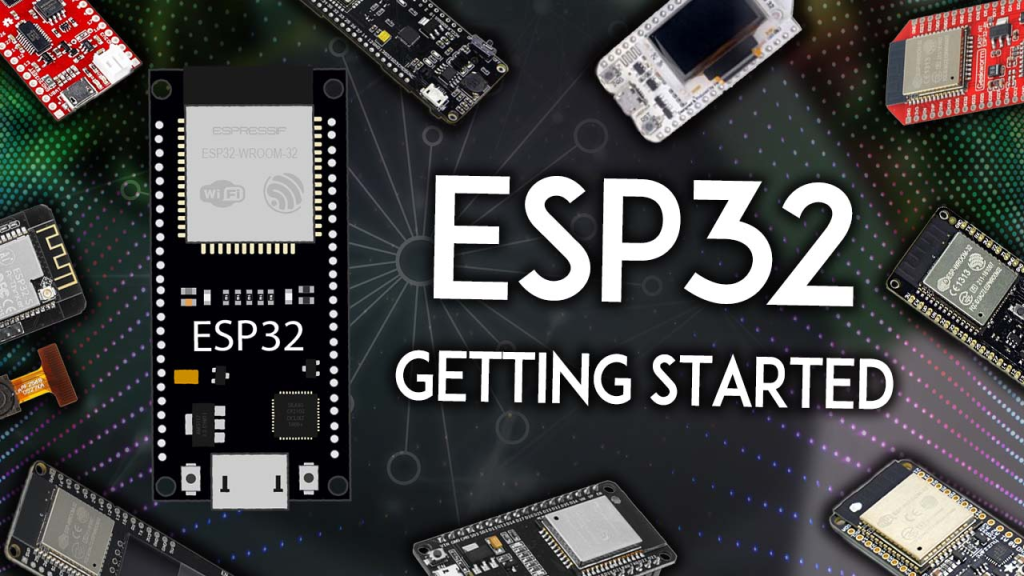
New to ESP32? Start here! The ESP32 is a series of low-cost and low-power System on a Chip (SoC) microcontrollers developed by Espressif that include Wi-Fi and Bluetooth wireless capabilities and dual-core processor. If you’re familiar with the ESP8266, the ESP32 is its successor, loaded with lots of new features.
New to the ESP32? You’re in the right place. This guide contains all the information you need to get started with the ESP32. Learn what is an ESP32, how to select an ESP32 board, how to get your first program working, and much more. Here’s what we’ll cover in this guide:
Table of Contents
Introducing the ESP32
ESP32 Specifications
ESP32 vs ESP8266
ESP32 Development Boards
How to choose an ESP32 development board?
What is the best ESP32 development board for beginners?
ESP32 DEVKIT DOIT
ESP32 GPIOs Pinout Guide
How to program the ESP32?
ESP32 with Arduino IDE
Introducing the ESP-32
First, to get started, what is an ESP32? The ESP32 is a series of chip microcontrollers developed by Espressif.
Why are they so popular? Mainly because of the following features:
Low-cost: you can get an ESP32 starting at $6, which makes it easily accessible to the general public;
Low-power: the ESP32 consumes very little power compared with other microcontrollers, and it supports low-power mode states like deep sleep to save power;
Wi-Fi capabilities: the ESP32 can easily connect to a Wi-Fi network to connect to the internet (station mode), or create its own Wi-Fi wireless network (access point mode) so other devices can connect to it—this is essential for IoT and Home Automation projects—you can have multiple devices communicating with each other using their Wi-Fi capabilities;
Bluetooth: the ESP32 supports Bluetooth classic and Bluetooth Low Energy (BLE)—which is useful for a wide variety of IoT applications;
Dual-core: most ESP32 are dual-core— they come with 2 Xtensa 32-bit LX6 microprocessors: core 0 and core 1.
Rich peripheral input/output interface—the ESP32 supports a wide variety of input (read data from the outside world) and output (to send commands/signals to the outside world) peripherals like capacitive touch, ADCs, DACs, UART, SPI, I2C, PWM, and much more.
Compatible with the Arduino “programming language”: those that are already familiar with programming the Arduino board, you’ll be happy to know that they can program the ESP32 in the Arduino style.
Compatible with MicroPython: you can program the ESP32 with MicroPython firmware, which is a re-implementation of Python 3 targeted for microcontrollers and embedded systems.
ESP-32 Specifications
If you want to get a bit more technical and specific, you can take a look at the following detailed specifications of the ESP32 (source: http://esp32.net/)—for more details, check the datasheet):
ESP32 module: ESP-WROOM-32
Wireless connectivity WiFi: 150.0 Mbps data rate with HT40
Bluetooth: BLE (Bluetooth Low Energy) and Bluetooth Classic
Processor: Tensilica Xtensa Dual-Core 32-bit LX6 microprocessor, running at 160 or 240 MHz
Memory:
ROM: 448 KB (for booting and core functions)
SRAM: 520 KB (for data and instructions)
RTC fast SRAM: 8 KB (for data storage and main CPU during RTC Boot from the deep-sleep mode)
RTC slow SRAM: 8KB (for co-processor accessing during deep-sleep mode)
eFuse: 1 Kbit (of which 256 bits are used for the system (MAC address and chip configuration) and the remaining 768 bits are reserved for customer applications, including Flash-Encryption and Chip-ID)
Embedded flash: flash connected internally via IO16, IO17, SD_CMD, SD_CLK, SD_DATA_0 and SD_DATA_1 on ESP32-D2WD and ESP32-PICO-D4.
0 MiB (ESP32-D0WDQ6, ESP32-D0WD, and ESP32-S0WD chips)
2 MiB (ESP32-D2WD chip)
4 MiB (ESP32-PICO-D4 SiP module)
Low Power: ensures that you can still use ADC conversions, for example, during deep sleep.
Peripheral Input/Output:
peripheral interface with DMA that includes capacitive touch
Security: hardware accelerators for AES and SSL/TLS
Main Differences Between ESP-32 and ESP-8266
Previously, we mentioned that the ESP32 is the ESP8266 successor. What are the main differences between ESP32 and ESP8266 boards?
The ESP32 adds an extra CPU core, faster Wi-Fi, more GPIOs, and supports Bluetooth 4.2 and Bluetooth low energy. Additionally, the ESP32 comes with touch-sensitive pins that can be used to wake up the ESP32 from deep sleep, and built-in hall effect sensor.
Both boards are cheap, but the ESP32 costs slightly more. While the ESP32 can cost around $6 to $12, the ESP8266 can cost $4 to $6 (but it really depends on where you get them and what model you’re buying).
So, in summary:
The ESP32 is faster than the ESP8266;
The ESP32 comes with more GPIOs with multiple functions;
The ESP32 supports analog measurements on 18 channels (analog-enabled pins) versus just one 10-bit ADC pin on the ESP8266;
The ESP32 supports Bluetooth while the ESP8266 doesn’t;
The ESP32 is dual-core (most models), and the ESP8266 is single core;
The ESP32 is a bit more expensive than the ESP8266.
For a more detailed analysis of the differences between those boards, we recommend reading the following article: ESP32 vs ESP8266 – Pros and Cons.
ESP32 Development Boards
ESP32 refers to the bare ESP32 chip. However, the “ESP32” term is also used to refer to ESP32 development boards. Using ESP32 bare chips is not easy or practical, especially when learning, testing, and prototyping. Most of the time, you’ll want to use an ESP32 development board.
These development boards come with all the needed circuitry to power and program the chip, connect it to your computer, pins to connect peripherals, built-in power and control LEDs, an antenna for wi-fi signal, and other useful features. Others even come with extra hardware like specific sensors or modules, displays, or a camera in the case of the ESP32-CAM.
How to Choose an ESP-32 Development Board?
Once you start searching for ESP32 boards online, you’ll find there is a wide variety of boards from different vendors. While they all work in a similar way, some boards may be more suitable for some projects than others. When looking for an ESP32 development board there are several aspects you need to take into account:
USB-to-UART interface and voltage regulator circuit. Most full-featured development boards have these two features. This is important to easily connect the ESP32 to your computer to upload code and apply power.
BOOT and RESET/EN buttons to put the board in flashing mode or reset (restart) the board. Some boards don’t have the BOOT button. Usually, these boards go into flashing mode automatically.
Pin configuration and the number of pins. To properly use the ESP32 in your projects, you need to have access to the board pinout (like a map that shows which pin corresponds to which GPIO and its features). So make sure you have access to the pinout of the board you’re getting. Otherwise, you may end up using the ESP32 incorrectly.
Antenna connector. Most boards come with an onboard antenna for Wi-Fi signal. Some boards come with an antenna connector to optionally connect an external antenna. Adding an external antenna increases your Wi-Fi range.
Battery connector. If you want to power your ESP32 using batteries, there are development boards that come with connectors for LiPo batteries—this can be handier. You can also power a “regular” ESP32 with batteries through the power pins.
Extra hardware features. There are ESP32 development boards with extra hardware features. For example, some may come with a built-in OLED display, a LoRa module, a SIM800 module (for GSM and GPRS), a battery holder, a camera, or others.
What is the best ESP32 development board for beginners?
For beginners, we recommend an ESP32 board with a vast selection of available GPIOs, and without any extra hardware features. It’s also important that it comes with voltage regular and USB input for power and upload code.
In most of our ESP32 projects, we use the ESP32 DEVKIT DOIT board, and that’s the one we recommend for beginners. There are different versions of this board with a different number of available pins (30, 36, and 38)—all boards work in a similar way.
Where to Buy?
You can check the following link to find the ESP32 DEVKIT DOIT board in different stores:
ESP32 DEVKIT DOIT board
Other similar boards with the features mentioned previously may also be a good option like the Adafruit ESP32 Feather, Sparkfun ESP32 Thing, NodeMCU-32S, Wemos LoLin32, etc.
ESP-32 DEVKIT DOIT
In this article, we’ll be using the ESP32 DEVKIT DOIT board as a reference. If you have a different board, don’t worry. The information on this page is also compatible with other ESP32 development boards.
The picture below shows the ESP32 DEVKIT DOIT V1 board, version with 36 GPIO pins.
Specifications – ESP-32 DEVKIT V1 DOIT
The following table shows a summary of the ESP32 DEVKIT V1 DOIT board features and specifications:
Number of cores
2 (dual core)
Wi-Fi
2.4 GHz up to 150 Mbits/s
Bluetooth
BLE (Bluetooth Low Energy) and legacy Bluetooth
Architecture
32 bits
Clock frequency
Up to 240 MHz
RAM
512 KB
Pins
30, 36, or 38 (depending on the model)
Peripherals
Capacitive touch, ADC (analog to digital converter), DAC (digital to analog converter), I2C (Inter-Integrated Circuit), UART (universal asynchronous receiver/transmitter), CAN 2.0 (Controller Area Netwokr), SPI (Serial Peripheral Interface), I2S (Integrated Inter-IC Sound), RMII (Reduced Media-Independent Interface), PWM (pulse width modulation), and more.
Built-in buttons
RESET and BOOT buttons
Built-in LEDs
built-in blue LED connected to GPIO2; built-in red LED that shows the board is being powered
USB to UART bridge
CP2102
his particular ESP32 board comes with 36 pins, 18 on each side. The number of available GPIOs depends on your board model.
To learn more about the ESP32 GPIOs, read our GPIO reference guide: ESP32 Pinout Reference: Which GPIO pins should you use
It comes with a microUSB interface that you can use to connect the board to your computer to upload code or apply power.
It uses the CP2102 chip (USB to UART) to communicate with your computer via a COM port using a serial interface. Another popular chip is the CH340. Check what’s the USB to UART chip converter on your board because you’ll need to install the required drivers so that your computer can communicate with the board (more information about this later in this guide).
This board also comes with a RESET button (may be labeled EN) to restart the board and a BOOT button to put the board in flashing mode (available to receive code). Note that some boards may not have a BOOT button.
It also comes with a built-in blue LED that is internally connected to GPIO 2. This LED is useful for debugging to give some sort of visual physical output. There’s also a red LED that lights up when you provide power to the board.
ESP-32 GPIOs Pinout Guide
The ESP32 chip comes with 48 pins with multiple functions. Not all pins are exposed in all ESP32 development boards, and some pins should not be used. The ESP32 DEVKIT V1 DOIT board usually comes with 36 exposed GPIOs that you can use to connect peripherals.
Power Pins
Usually, all boards come with power pins: 3V3, GND, and VIN. You can use these pins to power the board (if you’re not providing power through the USB port), or to get power for other peripherals (if you’re powering the board using the USB port).
General Purpose Input Output Pins (GPIOS)
Almost all GPIOs have a number assigned and that’s how you should refer to them—by their number.
With the ESP32 you can decide which pins are UART, I2C, or SPI – you just need to set that on the code. This is possible due to the ESP32 chip’s multiplexing feature that allows to assign multiple functions to the same pin.
If you don’t set them on the code, the pins will be configured by default as shown in the figure below (the pin location can change depending on the manufacturer). Additionally, there are pins with specific features that make them suitable or not for a particular project.
We have a detailed guide dedicated to the ESP32 GPIOs that we recommend you read: ESP32 Pinout Reference Guide. It shows how to use the ESP32 GPIOs and explains what are the best GPIOs to use depending on your project.
The placement of the GPIOs might be different depending on your board model. However, usually, each specific GPIO works in the same way regardless of the development board you’re using (with some exceptions). For example, regardless of the board, usually GPIO5 is always the VSPI CS0 pin, GPIO 23 always corresponds to VSPI MOSI for SPI communication, etc.
How to Program the ESP-32?
The ESP32 can be programmed using different firmware and programming languages. You can use:
Arduino C/C++ using the Arduino core for the ESP32
Espressif IDF (IoT Development Framework)
Micropython
JavaScript
LUA
Our preferred method to program the ESP32 is with C/C++ “Arduino programming language”. We also have some guides and tutorials using MicroPython firmware.
Throughout this guide, we’ll cover programming the ESP32 using the Arduino core for the ESP32 board. If you prefer using MicroPython, please refer to this guide: Getting Started with MicroPython on ESP32.
Programming ESP32 with Arduino IDE
To program your boards, you need an IDE to write your code. For beginners, we recommend using Arduino IDE. While it’s not the best IDE, it works well and is simple and intuitive to use for beginners. After getting familiar with Arduino IDE and you start creating more complex projects, you may find it useful to use VS Code with the Platformio extension instead.
If you’re just getting started with the ESP32, start with Arduino IDE.
Installing Arduino IDE
To run Arduino IDE, you need to install JAVA on your computer. If you don’t, go to the following website to download and install the latest version: http://java.com/download.
Downloading and Installing Arduino IDE
To download the Arduino IDE, visit the following URL:
https://www.arduino.cc/en/Main/Software
Go to the Arduino website and download the version for your operating system.
Windows: run the file downloaded and follow the instructions in the installation guide.
Mac OS X: copy the downloaded file into your application folder.
Linux: extract the downloaded file, and open the arduino-ide file that will launch the IDE.
Recommended reading: ESP-32 Development Boards Review and Comparison
Installing the ESP32 in Arduino IDE
To install the ESP32 board in your Arduino IDE, follow these next instructions:
1. In your Arduino IDE 2, go to File > Preferences.
2. Copy and paste the following line to the Additional Boards Manager URLs field.
3. Open the Boards Manager. You can go to Tools > Board > Boards Manager… or you can simply click the Boards Manager icon in the left-side corner.
4. Search for ESP32 and press the install button for esp32 by Espressif Systems version 3.X.
That’s it. It should be installed after a few seconds.
After this, restart your Arduino IDE.
Then, go to Tools > Board and check that you have ESP32 boards available.
Now, you’re ready to start programming your ESP32 using Arduino IDE.
Testing the Installation and Uploading Code to the ESP-32
Now, let’s check if the installation was successful and if we can upload new code to the ESP32 board.
We’ll simply upload an example sketch from the library of available examples.
Connect your ESP32 development board to your computer using a USB cable. If you have an ESP32 DEVKIT DOIT board, the built-in red LED will turn on. This indicates the board is receiving power.
Important: you must use a USB cable with data wires. Some USB cables from chargers or power banks are power only and they don’t transfer data—these won’t work.
With your Arduino IDE open, follow these steps:
1) Select your Board in Tools > Board menu or on the top drop-down menu, click on “Select other board and port…“
A new window, as shown below, will open. Search for your ESP32 board model.
Select the board model you’re using, and the COM port. In our example, we’re using the DOIT ESP32 DEVKIT V1. Click OK when you’re done.
Installing the USB Drivers
If you don’t see the COM Port in your Arduino IDE, you probably need to install the USB-to-UART drivers on your computer. Most ESP32 boards use either the CP210x or the CH340 chip depending on the board you’re using.
If you need to install the CP210x drivers, we recommend taking a look at this tutorial: Install ESP32/ESP8266 USB Drivers – CP210x USB to UART Bridge
2) Open the following example— it searches for wi-fi networks within the range of your board.
ESP32: File > Examples > WiFi (ESP32) > WiFiScan
3) A new sketch opens in your Arduino IDE:
4) Press the Upload button in the Arduino IDE. Wait a few seconds while the code compiles and uploads to your board.
Note: if you see a lot of dots on the debugging window, followed by an upload error, that means your board doesn’t go into flashing mode automatically. Click the Upload button again, and when you start seeing the dots on the debugging window, press the onboard BOOT button for a couple of seconds.
5) If everything went as expected, it will upload successfully after a few seconds. You’ll get a similar message:
6) Open the Arduino IDE Serial Monitor at a baud rate of 115200:
7) Press the ESP32 on-board Enable/RESET button and you should see the networks available near your board.
If you’re having issues uploading code to your ESP32 board, we recommend taking a quick look at the following troubleshooting guide: ESP32 Troubleshooting Guide.
ESP-32 Examples
In your Arduino IDE, you can find multiple examples for the ESP32. First, make sure you have an ESP32 board selected in Tools > Boards. Then, go to File > Examples and check out the examples under the ESP32 section.
Update the ESP-32 Core in Arduino IDE
It’s a good practice to periodically ensure you have the latest version of the ESP32 boards installed. In Arduino IDE 2, you’ll receive a pop-up notification prompting you to update whenever a new version becomes available.